
JEE Main 31 January 2024 Shift 2: Physics Question 19
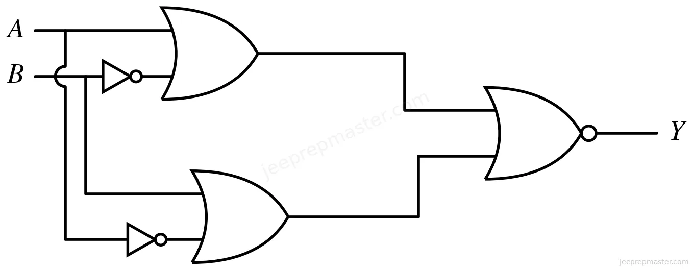
The output of the given circuit diagram is
| (1) A | B | Y | (2) A | B | Y |
|---|---|---|---|---|---|
| 0 | 0 | 0 | 0 | 0 | 0 |
| 1 | 0 | 0 | 1 | 0 | 1 |
| 0 | 1 | 0 | 0 | 1 | 1 |
| 1 | 1 | 1 | 1 | 1 | 0 |
| (3) A | B | Y | (4) A | B | Y |
|---|---|---|---|---|---|
| 0 | 0 | 0 | 0 | 0 | 0 |
| 1 | 0 | 0 | 1 | 0 | 0 |
| 0 | 1 | 0 | 0 | 1 | 1 |
| 1 | 1 | 0 | 1 | 1 | 0 |
Show answer and solution
Correct answer: Option 3
The upper OR gate gives , while the lower OR gate gives . These outputs feed a NOR gate, so .
Since and , the input OR expression is always 1. Thus for all four input pairs, matching option (3).